Showing posts with label computer graphics. Show all posts

Thursday, May 12, 2016

Thoughts about Regression analysis

Recently i watched a video about regression and probability, Here i am presenting some information from that.

Regression analysis is about establishing relationship between variables. That means there will be set of independent variables and corresponding dependent variables.

Example

let us denote price of a house using variable Y and factors affecting the price, such as area,age,location using variable X.

To make everything more simpler, let us take only the area of house as the independent variable, so there will be only one feature. Now we need to model the price (Y) of house. So that we can predict the price of an house if someone gives us the area. We can use the following simple equation to model that

H(t0,t1,i) =  t0 + t1 * X(i)  ----------------->  EQ(1)

t0 and t1 are constants.. ( when we have multiple factors, deciding the price other than area then it is possible to add more features to equation like  't0 + t1 * X1 + t2 * x2 + t2 * X1 * X2' or so on)

X(i) indicate sample number. That means if we have 100 data set containing 'area - price' pairs then X(5) will indicate the 5th area from the given data set.

If we plot EQ1(1), it will be a line for sure. So basically we are trying to find a line which will match with the expected set of house prices. See the following image.. where you can see a line which can be used to predict house price on a X value.


EQ(1) can be changed to higher degrees to achieve more complex predictions.  But simply adding more degrees will not help much. You also need to define the model in a more meaningful way.

Back to problem,
Now we need to find values for 't0' and 't1'  such that it will help to form a meaningful model.
For that we need to define cost function


-------------  EQ(2)


From EQ(2) we can see that , it is actually finding the sum of squared difference between expected value and our defined model (here it is based on line equation).

Aim must be to minimize EQ(2) , more we can minimize, less error will be , and our predicted line will be aligned more closely to the price data set. To do that we can use gradient descent method (other complicated solutions are also avilable, like conjugate gradient descent or BFGS , these are better than simple gradient descent , but complex to implement).

So for implementing gradient descent we need to find the gradient of function J with respect to t0 and t1 . You can use matlab to find that or find it manually. Following are the results


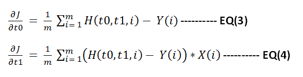
Now apply gradient descent to minimize function J.  Below shown the steps to do this in matlab.


% X valuessampleX = [ 0 1 2 3 4 5 6 7 8 9 10 11 12 13 14 15 16];% Y valuessampleY = [100 110 120 122 125 135 112 122 128 129 130 124 117 116 128 132 125];
% Y predicted using final model.resultY = [sampleY ];ss = size(sampleY);m = ss(2);resultC = zeros(ss(2),3);
cmap = hsv(1);
error = [];
theta0 = 50;theta1 = 1;
% main iteration loopfor i = 1:1:10000
% function HnewSampleY = theta0 + theta1 * sampleX;
deviation = sum((newSampleY - sampleY).^2);deviation  = deviation / (2*ss(2));error = [ error ;deviation ];
resultY = [newSampleY];colorPoints = zeros(m,3);colorPoints(1: end,1) = cmap(1,1);colorPoints(1: end,2) = cmap(1,2);colorPoints(1: end,3) = cmap(1,3);%resultC = [resultC;  colorPoints];resultC = [ colorPoints];
% derivative of J w.r.t t0theta0Gradient = sum(newSampleY - sampleY) / m;% derivative of J w.r.t t1theta1Gradient =  sum((newSampleY - sampleY).*sampleX ) / m;
% applying gradient descent operation to minimize Jtheta0 = theta0 - .01 * theta0Gradient;theta1 = theta1 - .01 * theta1Gradient;
end 

scatter([sampleX sampleX],[sampleY resultY],[],[ zeros(m,3);  resultC]);axis([0 50 -100 100]);hold; 
fprintf('\ncomputed error values\n');error

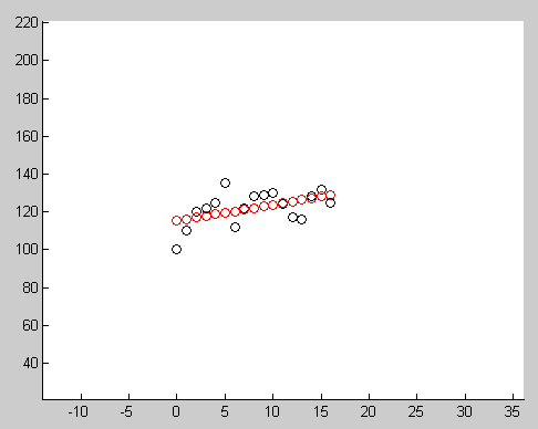
Below image show the result after running this code. Red circles indicate the points generated using final model, black circles indicates the input data.


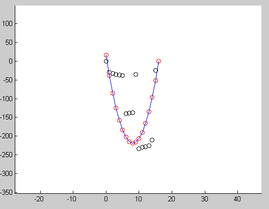
Another example showing how we can use this to fit a quadratic curve to input points.


Sunday, February 24, 2013

Histogram Equalization : A simple technique for improving low contrast images

I have been busy. Not getting much time to give enough attention to this. I am really worried about this and this makes me unhappy. But life must goes on. I can do what i want but i am not able to do.. It is an interesting thought. I am sure many of us still have this.(just had a wine)

What is histogram , it is a frequency showing some information in image. Due to some factors based on the equipment or lighting or whatever it is possible sometimes taken image will contain colors that uses near by gray values. That is is the image's gray levels are not really stretched to required level.

See some images here
These are images taken on low light or artificially generated. if you examine this these uses intensities that are around near by spectrum.That is why our eye is not able to perceive the amount of detail we want to interpret.  Histogram equalization is a very simple technique to stretch out this contrast by using a cumulative distributive function.

This CDF function is very simple, it means for the pixel with highest value it assigns a probability of 1, because it is cumulative  That is for the brightest pixel value( say 255) it sums probabilities of all pixels from 0 to 255 and it must be 1 it will be (for other pixel values it sum ups probabilities up to that pixel's value). So our CDF function is a monotonically increasing function.

I am attaching the mathematica code and results. so i don't have to explain.

yimage = Import["f:\\imtests\\lowContrast1.jpg"];
grayImg = ColorConvert[myimage, "GrayScale"];
mydata = ImageData[grayImg, "byte"];
temp = ImageDimensions[grayImg];
width = temp[[1]];
height = temp[[2]];
numberOfPixels = width*height;
histo = Array[0 &, 256];

(* compute histogram *)
m = mydata[[2]][[138]];
For[ i = 1 , i <= height, i++,
  For[ j = 1 , j <= width, j++,
    m = mydata[[i]][[j]];
    m = m + 1;
    histo[[m]] ++;
    ];
  ];

(* create cummlative distributive function to map pixels *)
cdf = Array[0 &, 256];
For[ i = 1, i <= 256, i++,
  sum = 0.0;
  For[ j = 1, j <= i, j++,
 
   sum = sum + histo[[j]] / numberOfPixels;
   ];
  sum = sum * 255;
  cdf[[i]] = sum;
  ];

(* plot cdf *)
ListLinePlot[cdf]

(* equalize histogram *)

orignalData = mydata;
(* change pixels in original image based on cdf function *)
For[ i = 1 , i <= height, i++,
  For[ j = 1 , j <= width, j++,
    m = mydata[[i]][[j]] + 1;
    mydata[[i]][[j]] = cdf[[m]]
    ];
  ];
Image[orignalData, "byte"]
Image[mydata, "byte"]


Outputs

CDF  function


Original image


Output image


See how good is the equalized image. but do not expect Histogram Equalization to perform this in all conditions. In general It is good for x-ray images. One other problem is it will also amplify the noise. So it better to remove the noise before passing to this.

Wednesday, October 24, 2012

3D Face creation in Android

Before 3 weeks  one  thought came to my mind, like for creating a 3D surface/object for face image using Opengl ES- Android. Recently I got some time to implement that.

The the basic idea is like this. Create a mesh surface and texture map it with the image of the face which you want on  it. Then provide/implement some tools to bevel up/down on these mesh preserving the smoothness of the surface. I don't want to mention too much details here, because i don't think it contains enough theories which needs explanation.

See the video below( taken with a web cam). May not have enough clarity. I implemented this app in Java only and it took almost 6 hours. After creating the 3D face object ,App will allow user to export it as OBJ format. But that part needs to be done and i am lazy. So Ii stopped further implementation :)


Is anybody  interested in the code?   ;). 

Thursday, April 12, 2012

MD2 animation

Before 2 weeks I added Md2 animation support to my engine. It was an easy task. MD2 has some predefined set of animations. MD2 is used by games like QuakeII,Sin, Solider Of Fortune .

See the  MD2  animations running with my engine(Video lacks clarity because my screen capture software not allows to record at high frame rate with good quality)


While coding MD2 loader i found that the skin path in the MD2 file is relative and sometimes entirely in some other directory. So we cannot rely on this path. In MD2 file they are trying to minimize the model data by using different techniques like having predefined normal vector set. The creators also store texture coordinates as short rather than float.you need to divide by the size of texture to get the real texture uv coordinates.

One other problem is with inconsistent naming convention of frames. say we have 120 frames , and in one Md2 file 10-20 frames contains animation for running data with name "Run001", but in some other file they use "Run__1"..  it would be better if the creators have made a standard for frame names.

Finally you can use blender modeler software to create MD2 animations.(i heard it is buggy :) , Thats ok Bugs are everywhere), 

Thursday, March 11, 2010

How to check a Point inside a Triangle


When i started to learn vector mathematics , i had found many methods to determine whether a point is inside a triangle or not.Easy method is not the fastest. This type of calculations are very important for making a fast graphics library.
Following are the methods which i remember now.
1. Using Cross Products
Take cross product between each triangle edge and the point to check. If the direction of cross product result is for the three edges that point is inside the triangle , otherwise not

2. Using the angle between the vectors made by point and triangle coordinates.If the sum of angle is 360 the point is inside , otherwise not.


3. Using Point and Plane test.See the figure. You need to know plane equation to understand it.


4. Using Bary centric Coordinates
This is the fastest of above. It involves checking the point in Bary centric coordinates system.


Monday, October 6, 2008

Collision detection using Separating Axis Theorem


Currently i am working on a graphics engine , which uses loose octree for occlusion culling as well as collision detection..

It works as i am expected. I have implemented  the SAT algoritham to test BOX-Triangle intersection test. It works well..Currently i am checking all the triangles inside the current camera node, It doesn't seems practical with detailes scene.

I need to add support for collision mesh( These mesh  are not rendered,they are just used for collision detection).Hmm.I can see the need for a level editor. Before that i am would like to respond my camera accoring to the geometry in the scene.


Following is the SAT code for triangle - Box intersection , I couldn't find any c++ code in internet ( Muller's is there , it is cryptic for me as well as it is not c++)

 template
<typename T>
Interfaces3D::InterSection CBBox<T>::IsInsideBox(
const Triangle<T>& refTri ) const
{

// If three points are inside the box, definitily the triangle is inside the ABBBox.
if( IsInsideBox( refTri.m_Pt1 ) && 
IsInsideBox( refTri.m_Pt2 ) && IsInsideBox( refTri.m_Pt3 ) )
   return Interfaces3D::InterSectionIn;

Math3D::vector<T> xAxis(1,0,0);
Math3D::vector<T> yAxis(0,1,0);
Math3D::vector<T> zAxis(0,0,1);

//..............................................................
// Intersection test using SAT (separating Axis test) algorithm.
//..............................................................
float fMin,fMax;
float fBoxMin,fBoxMax;
float fProjTri[3] = { 0,0,0 };
float fProjBox[2] = { 0,0 };

// First test is agnist the AABBox's cardianl axis.
fProjTri[0] = refTri.m_Pt1.x;
fProjTri[1] = refTri.m_Pt2.x;
fProjTri[2] = refTri.m_Pt3.x;

FindMinMax( fProjTri,3,fMin,fMax );

if( (fMin < m_XL && fMax < m_XL ) || (fMin > m_XR && fMax > m_XR ) )
return Interfaces3D::InterSectionOut; // the triangle is outside.

fProjTri[0] = refTri.m_Pt1.y;
fProjTri[1] = refTri.m_Pt2.y;
fProjTri[2] = refTri.m_Pt3.y;

FindMinMax( fProjTri,3,fMin,fMax );

if( (fMin < m_YB && fMax < m_YB ) || (fMin > m_YT && fMax > m_YT ) )
return Interfaces3D::InterSectionOut; // the triangle is outside.

fProjTri[0] = refTri.m_Pt1.z;
fProjTri[1] = refTri.m_Pt2.z;
fProjTri[2] = refTri.m_Pt3.z;

FindMinMax( fProjTri,3,fMin,fMax );

if( (fMin < m_ZF && fMax < m_ZF ) || (fMin > m_ZN && fMax > m_ZN ) )
return Interfaces3D::InterSectionOut; // the triangle is outside.
// Second test is agnist triangles normal.
Math3D::vector<T> vtNormal = refTri.m_Normal;

// project the triangle coordinates on this normal as well as the AABB corners.

// projecting Box's coordinates
Math3D::vector<T> vtRadius = GetTopLeftNear() - GetPosition();

float fExtent = vtNormal.Dot( vtRadius );
float fCenterBox = vtNormal.Dot( GetPosition() );
fProjBox[0] = fCenterBox + fExtent;
fProjBox[1] = fCenterBox - fExtent;

FindMinMax( fProjBox, 2,fBoxMin,fBoxMax );

// projecting triangle coordinates
fProjTri[0] = vtNormal.Dot( refTri.m_Pt1 );
fProjTri[1] = vtNormal.Dot( refTri.m_Pt2 );
fProjTri[2] = vtNormal.Dot( refTri.m_Pt3 );

FindMinMax( fProjTri, 3,fMin,fMax );
// Check for overlapping between pronected coordinates.
// if not overlapping , no intersection.
if( (fMin < fBoxMin && fMax < fBoxMin ) || (fMin > fBoxMax && fMax > fBoxMax ) )
return Interfaces3D::InterSectionOut; // the triangle is outside.

// Next possible SAT axis are the Cross product of each tri edges with
// box's cardinal axis.

Math3D::vector<T> satAxis[9];
Math3D::vector<T> vTmp = (refTri.m_Pt1 - refTri.m_Pt2);

// edge 0 and X,Y,Z axis
satAxis[0] = vTmp.Cross( xAxis).normalize() ;
satAxis[1] = vTmp.Cross( yAxis).normalize() ;
satAxis[2] = vTmp.Cross( zAxis).normalize() ;

// edge 1 and X,Y,Z axis
vTmp = (refTri.m_Pt3 - refTri.m_Pt2);
satAxis[3] = vTmp.Cross( xAxis).normalize() ;
satAxis[4] = vTmp.Cross( yAxis).normalize() ;
satAxis[5] = vTmp.Cross( zAxis).normalize() ;

// edge 2 and X,Y,Z axis
vTmp = (refTri.m_Pt1 - refTri.m_Pt3);

satAxis[6] = vTmp.Cross( xAxis).normalize() ;
satAxis[7] = vTmp.Cross( yAxis).normalize() ;
satAxis[8] = vTmp.Cross( zAxis).normalize() ;

for( int i = 0; i < 9 ; i ++ )
    {

fExtent = satAxis[i].Dot( vtRadius );
fCenterBox = satAxis[i].Dot( GetPosition() );
fProjBox[0] = fCenterBox + fExtent;
fProjBox[1] = fCenterBox - fExtent;
FindMinMax( fProjBox, 2,fBoxMin,fBoxMax );
 // projecting triangle coordinates
fProjTri[0] = satAxis[i].Dot( refTri.m_Pt1 );
fProjTri[1] = satAxis[i].Dot( refTri.m_Pt2 );
fProjTri[2] = satAxis[i].Dot( refTri.m_Pt3 );
FindMinMax( fProjTri, 3,fMin,fMax );
// check for overlapping on the SAT axis 
if( (fMin < fBoxMin && fMax < fBoxMin ) || (fMin > fBoxMax && fMax > fBoxMax ) ) 
        return Interfaces3D::InterSectionOut; // the triangle is outside. 
   } 

return Interfaces3D::InterSectionIntersect; 

}

Collision detection using SAT


Following is the SAT code for triangle - Box intersection , I couldn't find any c++ code in internet ( Muller's is there , it is cryptic for me as well as it is not c++)

template
<typename T>
Interfaces3D::InterSection CBBox<T>::IsInsideBox(
const Triangle<T>& refTri ) const
{

// If three points are inside the box, definitily the triangle is inside the ABBBox.
   if( IsInsideBox( refTri.m_Pt1 ) &&  IsInsideBox( refTri.m_Pt2 ) &&  IsInsideBox( refTri.m_Pt3 ) )
   return Interfaces3D::InterSectionIn;
   Math3D::vector<T> xAxis(1,0,0);
   Math3D::vector<T> yAxis(0,1,0);
   Math3D::vector<T> zAxis(0,0,1);

  //..............................................................
  // Intersection test using SAT (separating Axis test) algorithm.
  //..............................................................
  float fMin,fMax;
  float fBoxMin,fBoxMax;
  float fProjTri[3] = { 0,0,0 };
  float fProjBox[2] = { 0,0 };
   
 // First test is agnist the AABBox's cardianl axis.
 fProjTri[0] = refTri.m_Pt1.x;
 fProjTri[1] = refTri.m_Pt2.x;
 fProjTri[2] = refTri.m_Pt3.x; 
 FindMinMax( fProjTri,3,fMin,fMax );

 if( (fMin < m_XL && fMax < m_XL ) || (fMin > m_XR && fMax > m_XR ) )
     return Interfaces3D::InterSectionOut; // the triangle is outside.
 fProjTri[0] = refTri.m_Pt1.y;
 fProjTri[1] = refTri.m_Pt2.y;
 fProjTri[2] = refTri.m_Pt3.y;
 FindMinMax( fProjTri,3,fMin,fMax );

 if( (fMin < m_YB && fMax < m_YB ) || (fMin > m_YT && fMax > m_YT ) )
    return Interfaces3D::InterSectionOut; // the triangle is outside.
 fProjTri[0] = refTri.m_Pt1.z;
 fProjTri[1] = refTri.m_Pt2.z;
 fProjTri[2] = refTri.m_Pt3.z;

 FindMinMax( fProjTri,3,fMin,fMax );

 if( (fMin < m_ZF && fMax < m_ZF ) || (fMin > m_ZN && fMax > m_ZN ) )
    return Interfaces3D::InterSectionOut; // the triangle is outside.

 // Second test is agnist triangles normal. 
 Math3D::vector<T> vtNormal = refTri.m_Normal;
 // project the triangle coordinates on this normal as well as the AABB corners.
 // projecting Box's coordinates
 Math3D::vector<T> vtRadius = GetTopLeftNear() - GetPosition();

 float fExtent = vtNormal.Dot( vtRadius );
 float fCenterBox = vtNormal.Dot( GetPosition() );
 fProjBox[0] = fCenterBox + fExtent;
 fProjBox[1] = fCenterBox - fExtent; 
 FindMinMax( fProjBox, 2,fBoxMin,fBoxMax );

 // projecting triangle coordinates
 fProjTri[0] = vtNormal.Dot( refTri.m_Pt1 );
 fProjTri[1] = vtNormal.Dot( refTri.m_Pt2 );
 fProjTri[2] = vtNormal.Dot( refTri.m_Pt3 );

 FindMinMax( fProjTri, 3,fMin,fMax );

 // Check for overlapping between pronected coordinates.
 // if not overlapping , no intersection.
 if( (fMin < fBoxMin && fMax < fBoxMin ) || (fMin > fBoxMax && fMax > fBoxMax ) )
    return Interfaces3D::InterSectionOut; // the triangle is outside.
  
 // Next possible SAT axis are the Cross product of each tri edges with
 // box's cardinal axis.

 Math3D::vector<T> satAxis[9];
 Math3D::vector<T> vTmp = (refTri.m_Pt1 - refTri.m_Pt2);
 // edge 0 and X,Y,Z axis 
 satAxis[0] = vTmp.Cross( xAxis).normalize() ; 
 satAxis[1] = vTmp.Cross( yAxis).normalize() ;
 satAxis[2] = vTmp.Cross( zAxis).normalize() ;

 // edge 1 and X,Y,Z axis 
 vTmp = (refTri.m_Pt3 - refTri.m_Pt2);
 satAxis[3] = vTmp.Cross( xAxis).normalize() ;
 satAxis[4] = vTmp.Cross( yAxis).normalize() ;
 satAxis[5] = vTmp.Cross( zAxis).normalize() ;

 //  edge 2 and X,Y,Z axis
 vTmp = (refTri.m_Pt1 - refTri.m_Pt3);
 satAxis[6] = vTmp.Cross( xAxis).normalize() ;
 satAxis[7] = vTmp.Cross( yAxis).normalize() ;
 satAxis[8] = vTmp.Cross( zAxis).normalize() ;

 for( int i = 0; i < 9 ; i ++ )
  {
fExtent = satAxis[i].Dot( vtRadius );
fCenterBox = satAxis[i].Dot( GetPosition() );
fProjBox[0] = fCenterBox + fExtent;
fProjBox[1] = fCenterBox - fExtent;
FindMinMax( fProjBox, 2,fBoxMin,fBoxMax ); 
 // projecting triangle coordinates
            fProjTri[0] = satAxis[i].Dot( refTri.m_Pt1 );
            fProjTri[1] = satAxis[i].Dot( refTri.m_Pt2 );
            fProjTri[2] = satAxis[i].Dot( refTri.m_Pt3 );
            FindMinMax( fProjTri, 3,fMin,fMax );
           // check for overlapping on the SAT axis
           if( (fMin < fBoxMin && fMax < fBoxMin ) || (fMin > fBoxMax && fMax > fBoxMax ) )
               return Interfaces3D::InterSectionOut; // the triangle is outside.
  } 
return Interfaces3D::InterSectionIntersect;
}

Saturday, September 20, 2008

3DS file rendering


I have completed my 3ds scene rednering a few weeks before.  Below picture show it..

I could perfectly handle almost all 3ds related information and transparency. Now i have plan to do ray tracing to produce good quality image .

[ Thanks to artist-3d.com and max-realsms for their models ]


car

Thursday, July 17, 2008

Quadratic curve Interpolation

While reading a  book which explain different type of curves I couldn't see any description about qudratic curves( eventhough it is a good book) . Hence i decided to solve it by myself. That is what is shown below. :) . If you are looking for a simple curve this may be suffient . Qudratic curve offers only one control point (tangent)to control the shpae.

The simple Quadratic equation can be used to connect two point in space by a curve. The qudratic equation is simple and has the generic form at^2 + bt + C. Where a ,b,c can be any suitable quantity. Here i am taking it as a vector , and t is time( or any scalar).

we have two points in space , p0 and p1 , we want to draw a curve to connect these two points. So the question may arise how to control the curve position/direction. Okay , So you may be waiting for that third parameter .

So what is said earlier is f(t) = at^2 + bt + c. -------- (1)
While interpolating what we need is f(0) should give p0 (starting point) and f(1) should give p1 (end point).


f(0)  = p0 and f(1) = p1.
Thus putting 0 in equation (1) gives f(0) ->  c =  p0.
and 1 in equation (1) gives f(1) -> a+b+c = p1   --------(2)

 If we differentiate the equation (1) we will get   2at + b . As before we are assuming when t= 0 output is p0'

 ie f '(0) = p0' , which is 2a* 0 + b = p0' , thus we will get b = p0'
So just now we have solved two unknowns b and c,which is equal to p0' and p0 respectievly.
substituting b and c in Equation (2) gives

                                 a+ p0' + p0 = p1 , So a = p1 - p0' - p0
Holy cow! You just solved that equation , now you can smoothly interpoltate it by changing the paramter "t".
The final equation becomes t^2(p1-p0'-p0) + p0' * t + p0 .
At t = 0 it will give p0 and at t=1 it will give p1 as output. You can change p0' to change the shape of the curve. p0' is a vector , if its direction is same as p1-p0 vector the result will be straight line connectin p0 and p1 . Try changing t and p0' to get the desired results.

The below picture shows the curve drawn by this technique... The picture is unclear actually curve is smooth ( i don't know how to correct it ).
  quadc
 Good luck